Checking the ignition system
To test the operation of the electrical components of the ignition system, you must use a voltmeter and ohmmeter.
Connecting cables for the control device
■ Pull the plug out of the control device (Lynx. 3.44)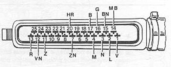 and check the circuits continuity with an ohmmeter according to the diagram in the figure 3.43.
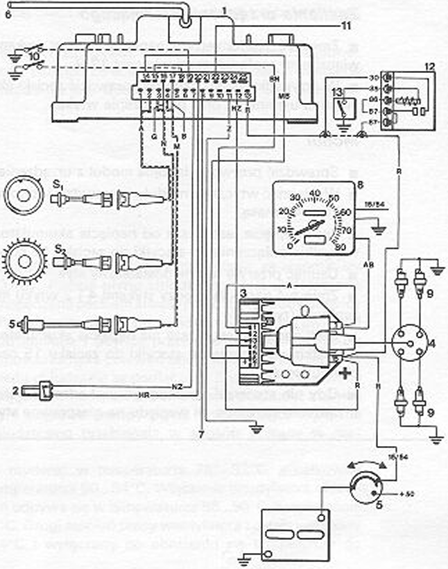
■ Search for circuit breaks and remove them.
Rotation sensor at the handwheel
■ Measure the resistance between contacts 3 and 16 plug. At 20ºC, it must be 618…748 Oh.
■ If the resistance exceeds the specified range, measure directly at the sensor. Replace cable or sensor, depending on the result.
■ The air gap between the sensor and the ZZ mark must be 0.4…1,0 Mm. To check it out, use a feeler gauge to set the plunger 1. cylinder to position ZZ. The gap size can be adjusted, loosening the handle.
ZZ position sensor at the pulley
■ Measure the resistance between contacts 1 and 2 plug. At 20 ° C, it must be 618…748 Oh. Otherwise, measure directly at the sensor. Depending on the result of replacing the cable or the sensor.
■ Set the air gap as for the rotation sensor.
Power supply to the control device
■ Measure the voltage between the contacts with a voltmeter 13 and 11 plug with the ignition on: must be 12 V.
■ In case of lack of voltage, check the battery terminals, especially the negative pole, and plug connection.
Module
■ Check the wires connecting the module to the control device.
■ Pull the plug out of the module and check the voltage between the contact with a voltmeter 4 and mass.
■ If the voltage is lower than the battery voltage, all connections from the ignition switch to the terminal should be checked 15 ignition coil.
■ Remove gap or insufficient contact.
■ Measure the voltage between the contacts 4 and 2 the module plug with the ignition on (Lynx. 3.45).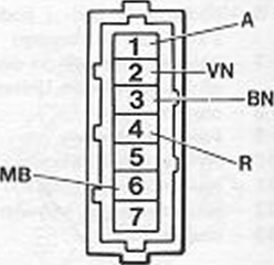
■ If the voltage is lower than the battery voltage, all connections from the ignition switch to the terminal should be checked 15 ignition coil and battery ground.
■ When no connection damage is found, the control device must be replaced, due to faulty contacts 11 and 12.
Knock sensor
■ Sensor defect manifests a tendency to knock burning or a decrease in power.
■ If there is a suspicion of sensor damage, replace it with a new one and perform a test drive for comparison.
■ Engine ringing can be caused by over-machining of the head (too much compression), incorrectly selected spark plugs or incorrect position sensor ZZ setting on the pulley.
Ignition coil and distributor
■ Disconnect the wires from the terminals before inspection 1 and 15 ignition coil.
■ Measure the resistance of the primary winding, which must be 0,31 …0.37 Oh.
■ Measure the resistance of the secondary winding, which must be 3300…4070 Oh.
■ Check the high-voltage wires with an ohmmeter. In the event of a defect, replace the entire set of cables.
■ The resistance of the splitter finger must be within 800…1200 Q
■ If no defect is found in the teams in question, it is necessary to replace the module.
Often, in the event of a malfunction of the ignition system, the fault location cannot be found unequivocally. It is then recommended to replace the actuator first (module), and if the defect persists, control device.